Introduction
In this article, we will describe what a membrane is, and what it is used for. A membrane is a semi-permeable barrier, used in microfluidic systems to control the transport of molecules and species in the system.
Different terms can be found instead of membrane in the litterature as the term of “filter”, “sieve”, or “porous support”. The term “filter” is used because the membrane allows the separation of particles of different sizes. The membrane can also be used as a shadow mask for the surface patterning. Besides, a membrane can also be used for the fabrication of 3D microfluidic devices, acting as a filter and able to interconnect two microfluidic channels above and below the membrane.
Membrane Technology
The membranes are used to control transport. When we transport particles out of the system, we can use the term of “separation”. When the transport is into the system, the term of “contacting” is employed. This transport is due to a chemical gradient: it can be a temperature gradient, a difference of pressure, concentration or even an electrical potential.
The morphology of the membrane is extremely important for transport: two kind of morphologies can be distinguished:
– a dense membrane
– a porous membrane
Dense membranes are used because they are permeable to single molecules. Wijmans and Backer established a model, calculating the permeability of the membrane, as the product of the diffusivity D and the solubility S in the membrane material.
P = D x S
The second parameter which defines dense membranes is the selectivity αij. This parameter defines the ratio of the pure permeability i and j.
As a consequence, the dense membranes are material dependent.
As far as the porous membranes are concerned, the transport a different. It doesn’t occur in the material itself, but in the pores of the membrane. Thus, the transport is directly dependent on the surface and volume porosity, pore size distribution and the tortuosity.
The tortuosity is a parameter used to correct the deviation of pores shape from perfect cylinders. As well as the dense membranes, we also characterize the membrane capacity with the permeability P. The other factor is called the retention R, which varies between 0 (there is no retention of a component i) and 1 (the component i is retained).
Another parameter that characterizes a porous membrane is the MWCO coefficient. It is defined as the molecular weight at which 90% of a component is retained by the membrane, and this coefficient gives an indication of the pore size.
Furthermore, membranes can be used in two modes:
– the “dead end” mode: In this mode, the particles and feed stream are completely transported through the membrane.
– the “continuous mode”: In this mode, either particles are retained, they are called ‘retentate’ , either the feed stream passes the membrane and is called ‘permeate’.
Both modes can be reached, depending on the application.
How to culture vascularized & immunocompetent 3D models in a standard Multiwell
Membrane in microfuidic systems
Multiple ways for integrating membranes on microfluidic devices have been performed these past 15 years.
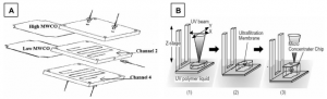
The first way would be the direct incorporation of membranes into the chip. This incorporation is done by either clamping or gluing the membrane on a layer or between two layers. In Fig 1 a clamping of two membranes is presented. As the simplest way to integrate a membrane in a microfluidic chip, the method also presents disadvantages: the fluids used (for instance inorganic substances) are combined with polymeric membranes and they can get sucked in between cover plates. The other problem is that when we glue the membrane, the glue can easily fill the pores of the membrane, thus blocking transport.
A method to overcome this problem is the use of micro stereo-lithography: a chip in 3D is prepared from a photo curable liquid polymer by using a UV beam. Thus, the membrane is put in a precursor solution, eliminating the need for a sealing step. Then, the non-crossed polymers are washed away after the chip preparation. Fig 1b shows the fabrication concept.
There are other ways to integrate a membrane into a microfluidic chip, such as the fabrication of a membrane in tisu, or the membrane preparation as part of a chip fabrication process, or a membrane made just with the chip material (for exemple, PDMS (polydimethylsiloxane) has been used as a membrane).
These methods will not be described in this article.
How to select a membrane for microfluidic application
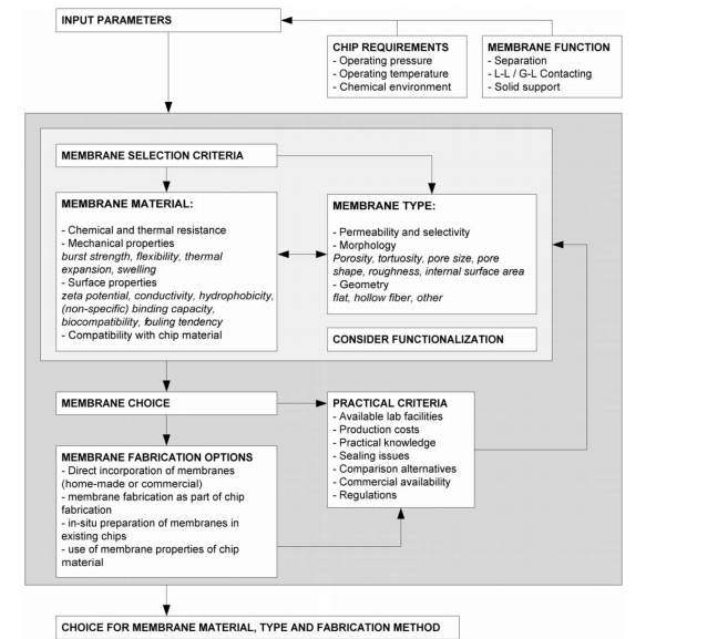
There are multiple kinds of membranes used recently for biological applications (polypropylene, polyethersulfone, cellulose acetate, polycarbonate, PTFE, etc.). We shall first choose the best membrane material and type for our targeted application. Fig 2 is showing a scheme that can be used in the selection process.
FAQ
A membrane is described as a semi-permeable barrier. It is used in microfluidic systems. Its purpose is to control the transport of molecules and species within the system. Other terms, such as "filter," "sieve," or "porous support," may be found in literature instead of "membrane". The term "filter" is applied because the membrane permits the separation of particles based on their different sizes. Membranes can also be employed for surface patterning, where they act as a shadow mask. Additionally, a membrane can be used during the fabrication of 3D microfluidic devices. In this application, it is able to interconnect two microfluidic channels, one above and one below the membrane.
Membranes are utilized to control transport. A distinction is made between "separation," which is transport out of the system, and "contacting," which is transport into the system. This transport is caused by a chemical gradient. Several types of gradients can be the cause of this movement. Examples include a temperature gradient or a difference in pressure. A difference in concentration can also be the cause. An electrical potential difference is another example of a chemical gradient that results in transport. The specific application determines which mode of transport is used and what gradient is present.
The morphology of the membrane is important for transport, and two kinds are distinguished. Dense membranes are permeable to single molecules. With these, transport occurs in the material itself, not through holes. The permeability ($P$) of a dense membrane is calculated as the product of diffusivity ($D$) and solubility ($S$). As a result, dense membranes are considered material dependent. The second type is the porous membrane. For porous membranes, transport happens within the pores of the membrane. This transport is therefore dependent on the surface and volume porosity, the distribution of pore sizes, and the tortuosity. Tortuosity is a parameter that corrects for the deviation of pore shapes from perfect cylinders. Porous membranes are also characterized by retention ($R$), which ranges from 0 (no retention) to 1 (full retention), and the MWCO coefficient.
Several methods for integrating membranes into microfluidic devices have been performed. The first method is the direct incorporation of the membrane into the chip. This can be done by either clamping or gluing the membrane onto a layer or between two layers. While clamping is the simplest way, it has disadvantages, as fluids may be sucked in between the cover plates. If glue is used, it can easily fill the pores of the membrane. This filling of the pores blocks the transport. A method to overcome these problems is the use of micro stereo-lithography. In this process, a 3D chip is prepared from a photo-curable liquid polymer using a UV beam. The membrane is put in a precursor solution, which eliminates the need for a separate sealing step. After the chip is prepared, the non-crossed polymers are washed away.